Beschreibung
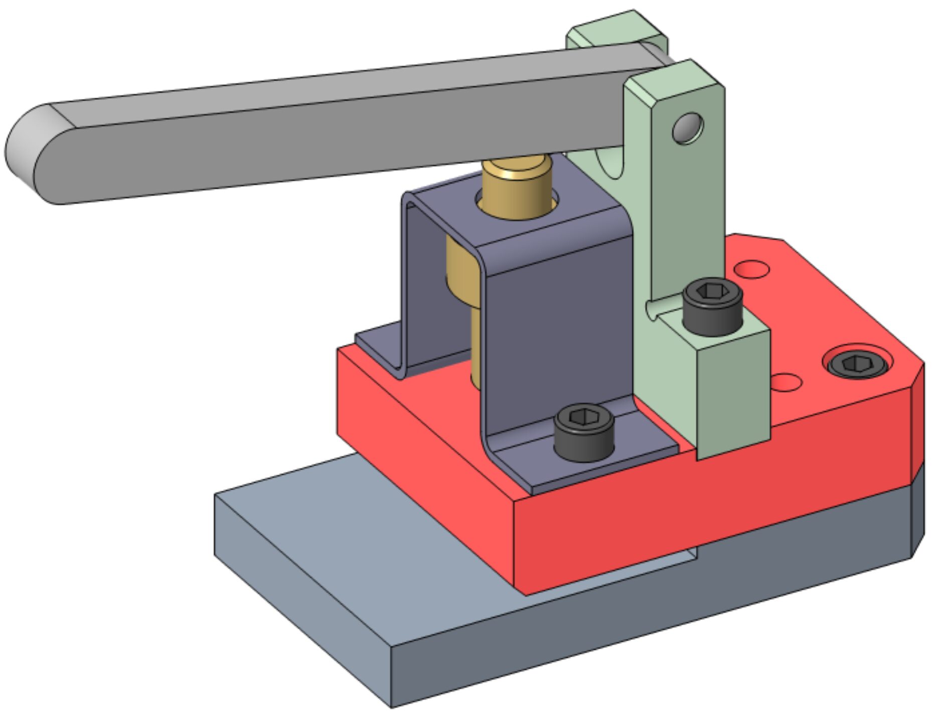
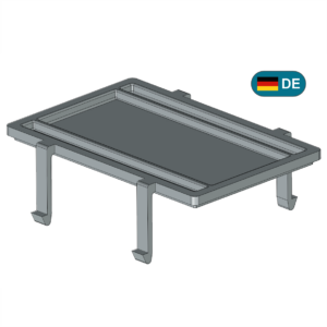
Here, we specify a bearing plate that is part of the “hole punch” assembly, as typically used in final examinations for metalworking apprenticeship programs.
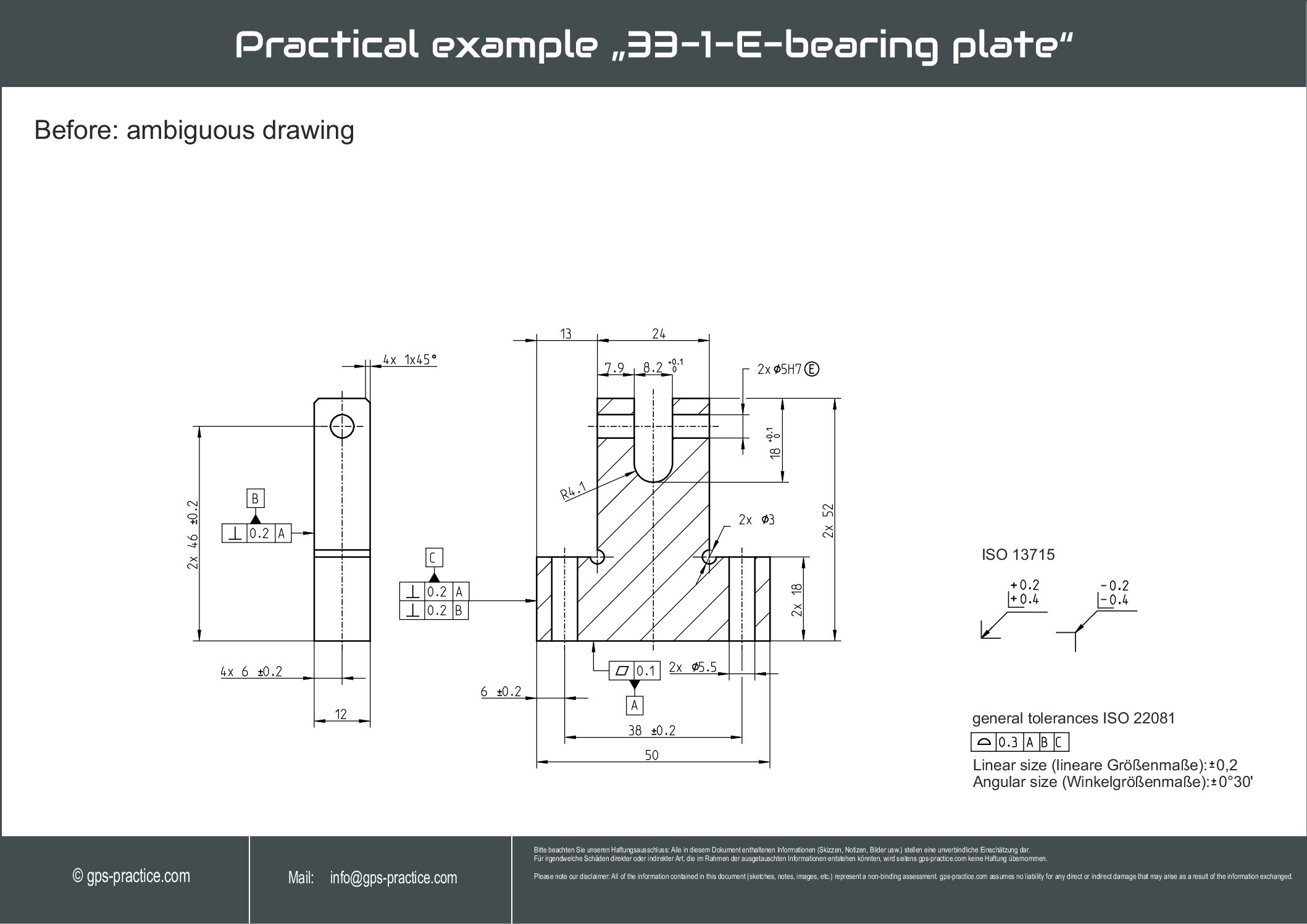
Using a before-and-after comparison, we demonstrate how an initially ambiguous drawing is transformed into an
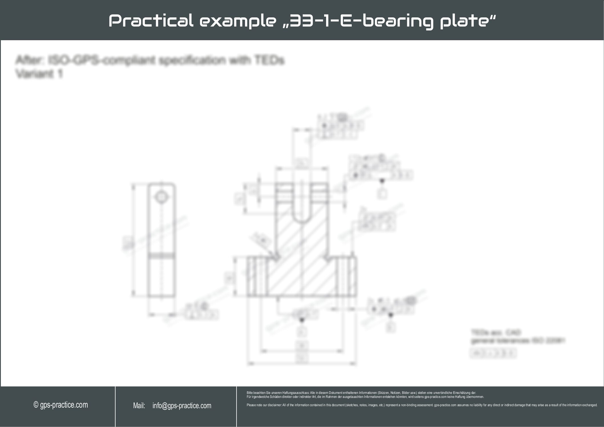
ISO-GPS-compliant and therefore function-oriented representation. Among other aspects, assembly intentions are made visible through unambiguous specifications.
This clearly illustrates the potential negative effects that ambiguous drawings can have on functionality.
Length of explanation video (Step by Step guide) : Approx. 26 min.
Variants: Yes – 2 Variants
Difficulty Level: Variant 1: Suitability 1 | Variant 2: Suitability 1-2
Description of the level of difficulty (suitability for the user):
1 – The user has basic knowledge but has not yet used ISO GPS frequently in practice and takes first steps.
2 – The user has basic knowledge but is not proof about using ISO GPS and would like to gain more general confidence.
More „special“ or complex modifiers (these are usually listed in the example description) are applied selectively.
3 – The user has sufficient knowledge, can already use frequently used ISO GPS tools without difficulty,
and would like to deepen knowledge selectively based on typical functional descriptions,
which is usually also product-specific (e.g., snapping features (latching hooks) on a plastic injection-molded part, special demand hole patterns, i.e. multi-level patterns etc.)
used in the example (i.e., listed in the description) (e.g., direction only or certain combinations of dimensional tolerancing, as well as SIM or similar modifications).
4 – The user has extensive knowledge, has been working with ISO GPS for a long time,
and would like to learn about very specific applications or modification operations, which usually describe more complex functional requirements and products.
This requires, for example, situation features, reference elements, filter information, association modifiers etc.